Witte Software® https://www.modbustools.com
2025-01-22
1. Modbus Slave
Modbus Slave is for simulating up to 100 slave devices in 100 windows!. Speed up your PLC programming with this simulating tools. Start programming and test before you receive your slave device from supplier. Data contained with any open document is accessible to the master application. Same user interface as Modbus Poll.
Monitoring of serial traffic. OLE Automation for interfacing with Visual Basic, Excel etc. To interpret and show the Modbus data according to your specific requirements. E.g. edit your slave data in Excel. Try the Excel example.xls included with the program.
Each window opened within Modbus Slave may be configured to represent data from the same or different slave nodes.
1.1. System requirements for Modbus Slave
- Hardware requirements
-
Processor; 1 GHz or faster recommended
1 GB RAM
5 MB of available hard drive space
1024 x 768 display resolution - OS requirements
-
All Windows versions from Windows 7 to Windows 11 are supported.
Modbus Slave version 8 runs on Windows XP.
1.1.1. Silent install
Silent install require no user intervention and have no user interface. The user doesn’t see any dialog and isn’t asked any questions.
Use the command line /S switch.
1.2. End User License Agreement
You should carefully read the following terms and conditions before using Modbus Slave. Unless you have a different license agreement signed by Witte Software, your use of this software indicates your acceptance of this license agreement and warranty. If you do not accept these terms you must cease using this software immediately.
Copyright.
Modbus Slave ("The Software") is copyright 2002-2025 by Witte Software, all rights reserved.
Evaluation and Registration.
This is not free software. You are hereby licensed to use the Software for evaluation purposes without
charge for a period of 30 days.
If you use the Software after the 30 day evaluation period a registration fee is required.
Unregistered use of the Software after the 30-day evaluation period is in violation of U.S. and international copyright laws.
One registered copy of the Software may either be used by a single person who uses the software personally on one or more computers, or installed on a single computer used by multiple people, but not both.
For information on order and pricing, please visit https://www.modbustools.com/order.html
Modbus Slave licenses are perpetual. Once you buy a license to a specific major version, and as long as you abide by the license agreement, you can use that version forever with no additional cost.
Distribution.
Provided that you do not include your License Key you are hereby licensed to make copies of the Software;
give exact copies of the original to anyone; and distribute the Software in its unmodified form via
electronic means. You are specifically prohibited from charging for any such copies.
LIMITED WARRANTY.
THE SOFTWARE IS PROVIDED AS IS AND WITTE SOFTWARE DISCLAIMS ALL WARRANTIES
RELATING TO THIS SOFTWARE, WHETHER EXPRESSED OR IMPLIED, INCLUDING BUT NOT LIMITED TO ANY IMPLIED
WARRANTIES OF MERCHANTABILITY AND FITNESS FOR A PARTICULAR PURPOSE.
LIMITATION ON DAMAGES.
NEITHER WITTE SOFTWARE NOR ANYONE INVOLVED IN THE CREATION, PRODUCTION, OR DELIVERY OF THIS SOFTWARE SHALL
BE LIABLE FOR ANY INDIRECT, CONSEQUENTIAL, OR INCIDENTAL DAMAGES ARISING OUT OF THE USE OR INABILITY
TO USE SUCH SOFTWARE EVEN IF WITTE SOFTWARE HAS BEEN ADVISED OF THE POSSIBILITY OF SUCH DAMAGES OR
CLAIMS. IN NO EVENT SHALL WITTE SOFTWARE’S LIABILITY FOR ANY DAMAGES EXCEED THE PRICE PAID FOR THE
LICENSE TO USE THE SOFTWARE, REGARDLESS OF THE FORM OF CLAIM. THE PERSON USING THE SOFTWARE BEARS
ALL RISK AS TO THE QUALITY AND PERFORMANCE OF THE SOFTWARE.
2. Modbus Slave Features
2.1. Connections
Modbus Slave read/write data from devices using:
-
Modbus RTU or ASCII on RS232 or RS485 networks. (USB/RS232/485 Converter)
-
Modbus TCP/IP
-
Modbus Over TCP/IP. (Modbus RTU encapsulated in a TCP packet)
-
Modbus UDP/IP
-
Modbus Over UDP/IP. (Modbus RTU encapsulated in a UDP packet)
2.2. Supported Modbus Functions
-
01 (0x01) Read Coils
-
02 (0x02) Read Discrete Inputs
-
03 (0x03) Read Holding Registers
-
04 (0x04) Read Input Registers
-
05 (0x05) Write Single Coil
-
06 (0x06) Write Single Register
-
08 (0x08) Diagnostics (Serial Line only)
-
11 (0x0B) Get Comm Event Counter (Serial Line only)
-
15 (0x0F) Write Multiple Coils
-
16 (0x10) Write Multiple Registers
-
17 (0x11) Report Server ID (Serial Line only)
-
22 (0x16) Mask Write Register
-
23 (0x17) Read/Write Multiple Registers
-
43 / 14 (0x2B / 0x0E) Read Device Identification
2.3. Display formats
Each cell can be individual formatted.
-
Signed 16-bit register
-
Unsigned 16-bit register
-
Hex
-
Binary
-
32-bit signed integer with any word/byte order
-
32-bit unsigned integer with any word/byte order
-
64-bit signed integer with any word/byte order
-
64-bit unsigned integer with any word/byte order
-
32-bit float with any word/byte order
-
64-bit double float with any word/byte order
2.4. Miscellaneous features
-
OLE/Automation for interfacing with Excel VBA, Python etc.
-
Monitoring of data traffic
-
Print and print preview
-
Font selection
-
Conditional colors
-
Scaling
-
Real time charting
-
Save/Open workspace
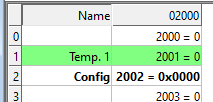
3. Overview
Modbus Slave uses a multiple document interface. That means several windows can be opened. Each one with different data contents for simulation of different slave devices at the same time.
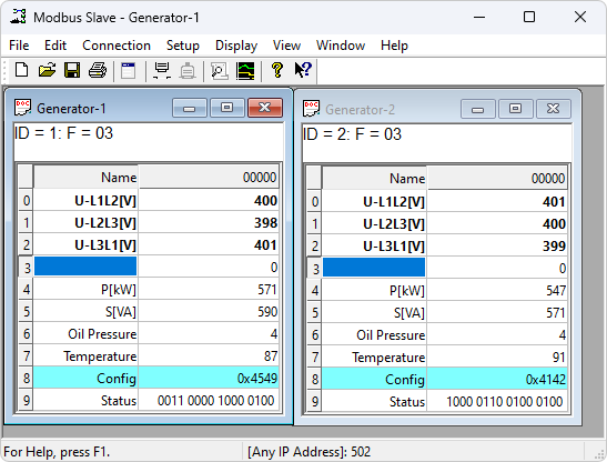
This picture shows two open windows. One simulating 10 Holding registers from address 0 (40001) slave id 1 and another simulating 10 Holding registers from address 0 (40001) slave id 2.
3.1. Help from anywhere
Press F1 and get context sensitive help on a topic associated with the current selected item.
SHIFT + F1 invokes a special "help mode" in which the cursor turns into a help cursor (arrow + question mark). The user can then select a visible object in the user interface, such as a menu item, toolbar button, or window. This opens help on a topic that describes the selected item.
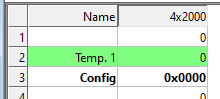
3.2. Name cells
Here you can type any text for designation of the value cells. You can also copy/paste text from Excel cells.
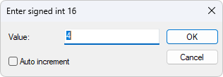
3.3. Value cells
Show the data values of the Modbus registers. If you double click a value cell a dialog box lets you enter a new value to the value cell. Typing a number in a value cell shows the input dialog as well.
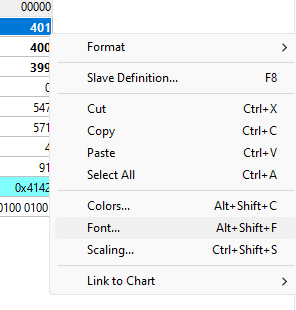
3.4. Change font
- To change the font you have 2 options
-
-
Select the cells to be changed and then right click.
-
Select the cells to be changed and then Menu→Display→Font.
-
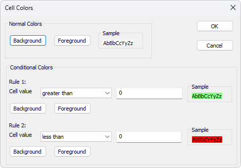
3.5. Conditional colors
Conditional colors help you visually show values in specific ranges.
- 3 color options
-
-
Default color: This color is used if none of the conditional colors evaluates to true.
-
Rule 1: This color selection is used if the expression evaluates to true. Rule 1 has precedence over rule 2.
-
Rule 2: This color selection is used if the expression evaluates to true.
-
- 7 Comparison operators
-
-
not used
-
equal to
-
greater than
-
less than
-
greater than or equal to
-
less than or equal to
-
and
-
The "and" operator cannot be used when the data type is of float or 32 bit long type. The condition value is entered as a hex number if "and" is selected. It evaluates to true if any of the bits in both the cell and the condition value is 1.
3.5.1. Color example
Green color if the cell value is greater than 0 and red if less than 0.
3.6. Scaling
Scaling helps you scale raw values to human readable values. Scaling works only for signed and unsigned 16/32 bit integers.
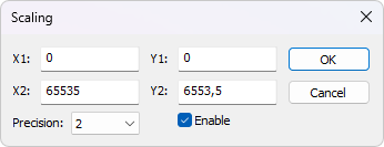
- (X1,Y1) and (X2,Y2)
-
A line passing through the two points (X1,Y1) and (X2,Y2)
\$Slope = m = (Y2 - Y1) / (X2 - X1)\$
- Line equation
-
\$Y = m * (X - X1) + Y1\$
- Precision
-
Number of digits after the decimal point.
- Enable
-
Must be enabled to scale the value from the Modbus server/slave. Scaling is automatically disabled if other than a 16/32 bit integer display format is selected.
3.7. Real time charting
The chart can plot 12 series in real time with up to 100000 points in each series.
3.8. Open a new window
To open another window you have 3 options:
-
Press CTRL+N
-
Select new in the file menu
-
Press
 on the tool bar
4. Connection dialog
To open the connection dialog you have 2 options:
-
Press F3
-
Select connect from the connection menu
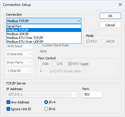
4.1. Connection
There are 5 different connection types:
-
Serial:
Modbus over serial line. RS232 or RS485. A USB serial converter can be used. -
Modbus TCP/IP:
Select TCP/IP if you want to communicate with a MODBUS TCP/IP network. In this case, slave ID is the same as the Unit ID used in MODBUS TCP/IP.
The port number is default 502. -
Modbus UDP/IP:
Select UDP/IP if you want to communicate with a MODBUS UDP/IP network. This is the same as Modbus TCP/IP but the connection less UDP protocol is used instead. -
Modbus RTU Over TCP/IP:
This is a RTU message sent over a TCP/IP network instead of serial lines. -
Modbus RTU Over UDP/IP:
This is a RTU message sent over a UDP/IP network instead of serial lines.
|
Connection type 3-5 is not standard Modbus as specified by www.modbus.org but they are added for convenience. |
Depending on your selection some other settings will be grayed.
4.2. Serial Settings
Use these parameters to set serial port settings. They are only available if the connection type is "Serial Port".
|
In Windows it is not possible to measure the 3.5 character idle time between two Modbus frames. That means that it may not be possible to use Modbus Slave in parallel with another slave device unless you are sure that the delay in the slave is > 20ms. |
- Mode
-
Use this option to select RTU or ASCII mode. Default RTU.
- DSR
-
Specifies whether the DSR (data-set-ready) signal is monitored for output flow control. If this member is TRUE and DSR is turned off, output is suspended until DSR is sent again.
- CTS
-
Specifies whether the CTS (clear-to-send) signal is monitored for output flow control. If this checkbox is enabled and CTS is turned off, output is suspended until CTS is sent again.
- RTS Toggle
-
Specifies that the RTS line will be high if bytes are available for transmission. After all buffered bytes have been sent, the RTS line will be low.
You can use this to switch direction if you have a 232/485 converter without automatic direction switch.
|
The use of RTS controlled RS232/RS485 converters should be avoided if possible. It is difficult to determine the exact time when to switch off the transmitter with non real-time operating systems like Windows and Linux. If it is switched off too early characters might still sit in the FIFO or the transmit register of the UART and these characters will be lost. Hence the slave will not recognize the message. On the other hand if it is switched off too late then the slave’s message is corrupted and the master will not recognize the message. |
4.3. TCP/IP Server
TCP/IP server settings are only available when using an Ethernet connection.
- IP Address
-
Specify which IP address to listen to. This is useful if you have several network connections on your PC. Each instance of Modbus Slave can listen to a specific network. Default is local host 127.0.0.1
- Any Address
-
Check this on if you want Modbus Slave to listen on all networks.
- IgnoreUnit ID
-
Many PLC devices will ignore this field, and most clients default value to zero. However gateways or specialized programs can use the unit number to indicate what type of processing is desired.
- Port
-
Server port number. Default 502
5. Slave definition
Use this command to define the data array to be defined for the active window.
To open the Slave Definition dialog you have 3 options:
-
Press F8
-
Select "Slave Definition" from the Setup menu
-
Press
 on the tool bar
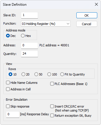
5.1. Slave ID
Range 1 to 255. (MODBUS protocol specifications say 247). The value 0 is also accepted to communicate directly to a MODBUS/TCP or MODBUS/UDP device.
5.2. Function code
You can select 1 of 4 function codes.
-
01: Read coils (0x). Accepts write functions 05 and 15
-
02: Read discrete inputs (1x)
-
03: Read holding registers (4x). Accepts write functions 06, 16, 22 and 23
-
04: Read input registers (3x)
5.3. Address
Addresses in the Modbus protocol are confusing! Some protocol specifications use the protocol/message address and others use device addressing.
5.3.1. Protocol/message address
Some protocol specifications use the protocol/message address counting from 0 to 65535 along with a function code. This is also what the new Modbus specifications use. This is the address inside the message sent on the wire.
Modbus Slave use protocol/message address counting from 0 to 65535.
5.3.2. Device address
Some protocol specifications use device address/registers. Registers counts from 1. The first digit describes the function to be used. That means the device address 40101 is identified by address 100. The "4" means Holding registers and 4x registers counts from 1. Therefore the ‘4XXXX’ reference is implicit. And even more confusing: 4x means function code 03 and 3x means function code 04!
5.3.3. 5 digits vs. 6 digits addressing
The address format 4x counts from 40001 to 49999. The next address is not 50000. In the old days 9999 addresses was enough. There are cases where 9999 is not enough. Then a zero is added. 40101 becomes 400101 and so on. This is called 6 digits addressing or extended addressing.
This is not a problem with Modbus Slave. 410001 become 10000. The "4" is thrown away and the rest 10001 is decremented by 1 as we count from 0 instead of 1.
5.3.4. Address examples
These examples show how to set up Modbus Slave if a specification uses device addresses.
Define Holding Registers
You want to define 20 registers from device address 40011 from slave ID 2. From the "4" we know this is function 03 "Read Holding Registers".
-
Slave ID = 2
-
Function = "03 Read Holding Registers (4x)"
-
Address = 10 (11 minus 1)
-
Quantity = 20
Define Discrete Inputs
You want to Define 1000 coils from address 110201 from slave ID 5. From the "1" we know this is function 02 "Read Discrete Inputs"
-
Slave ID = 5
-
Function = "02 Read Discrete Inputs (1x)"
-
Address = 10200 (10201 - 1)
-
Quantity = 1000
5.4. Hide name columns
Hide all name columns. This is convenient to make more space if they are not used.
5.5. Address in cell
If enabled, the address is also shown in the value cell like: 2000 = 00000
5.6. PLC Addresses (Base 1)
This option will show the addresses as device addresses.
5.7. Rows
Specify the number of rows in the grid you prefer.
6. Real time Charting
Use this command to plot up to 12 data series in a chart in real time.
The real time chart is high speed and capable of drawing a new line as fast as new data is received.
| All chart settings are saved in the workspace file. Save/Open Workspace |
To open the Real time charting dialog you have 2 options:
-
Press Alt + R
-
Select "Real time Charting" from the Display menu
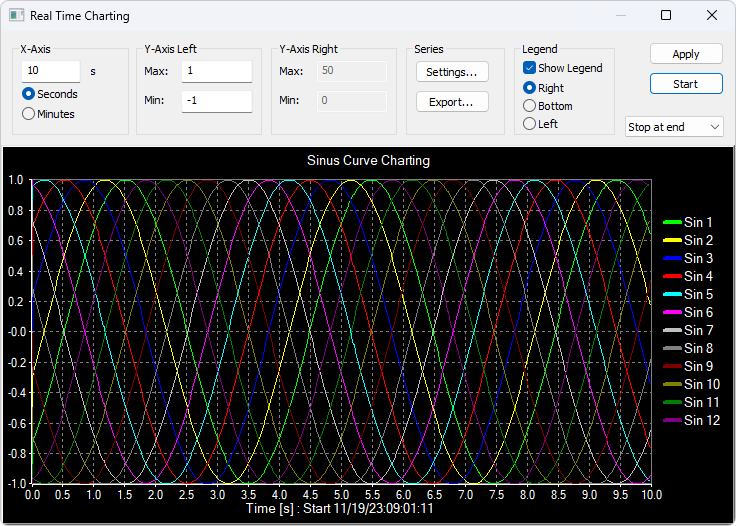
The X-Axis displays the number of seconds since the chart was started.
When the points reach the end of the chart there are 3 options:
-
Stop at end: The charting stops.
-
Restart at end: The charting starts all over again.
-
Continue: It continues until it reaches the max number of points or stop is pressed.
-
Auto Panning: As Continue but panning half a chart to the left.
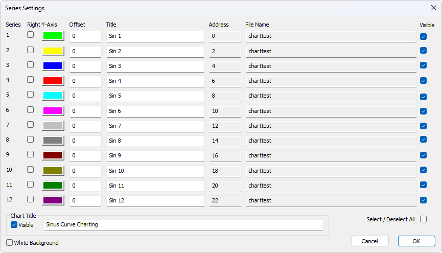
6.1. Settings
By default all 12 series are linked to the left Y-Axis. Check the "Right Y-Axis" check box if you want to link a series to the right Y-Axis.
- Specify
-
-
Colors
-
Right Y-Axis
-
Title. If title is empty it is initialized with the name from the reading window
-
Offset
-
- Show
-
-
File name
-
Address
-
The offset is useful to align data points on the same Y-Axis. For example, data points that are either 0 or 1 can be offset so they are not drawn on top of each other.
6.2. Zoom function
Zooming in on the chart can be useful if you want to see more details. The zoom is controlled with the left mouse button. To zoom a specific part of the chart, simply left-click on the chart (this will be the upper-left corner of the zoomed rectangle) and drag to the bottom-right. A rectangle will appear. As soon as you release the mouse button, the axes will automatically adjust themselves to the region you have selected.
If you left-click on the chart (like for starting a zoom) but if you move to the top-left corner instead, all the modifications done with the zoom and pan features will be canceled (the chart will be in the state it was before the manipulations with the pan and zoom).
6.3. Pan function
To pan the control, right-click somewhere on the control and move the mouse. The point under the mouse will follow the movement of the mouse.
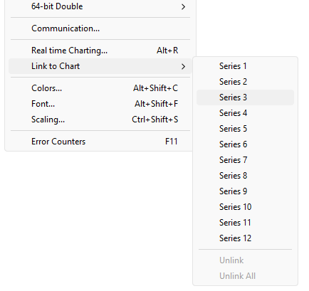
6.4. Link data to the chart series
The chart doesn’t know what data to use unless you link a Modbus data cell to one of the 12 series. To do this, select a value cell and choose "Link to chart" from Menu→Display.
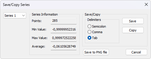
6.5. Export series
Save series data to disk or copy to clipboard. Paste the data direct in Excel for further processing.
The file is given a .csv extension despite the use of a non-comma field separator.
Delimiters: Select the character that separates values in your text file. Use tab delimiter when copy/paste to Excel.
- Furthermore some additional information is given.
-
-
Number of points
-
Max point value
-
Min point value
-
Average point value
-
7. Display formats
Mark the cells to be formatted. Select one of the 28 display formats from the display menu.
7.1. Native Modbus registers
The 16-bit Modbus registers can be displayed in 4 different modes.
-
Signed
-
Unsigned
-
Hex
-
ASCII - Hex
-
Binary
7.2. 32-bit signed integer
This combines 2 16-bit Modbus registers. It can be displayed in 4 different word/byte orders.
-
Signed integer Big-endian
-
Signed integer Little-endian
-
Signed integer Big-endian byte swap
-
Signed integer Little-endian byte swap
- Example
-
Byte Order: AB CD (Big-endian)
The decimal number 123456789 or in hexadecimal 07 5B CD 15
Order as they come over the wire in a Modbus message: 07 5B CD 15
7.3. 32-bit unsigned integer
This combines 2 16-bit Modbus registers. It can be displayed in 4 different word/byte orders.
-
Unsigned integer Big-endian
-
Unsigned integer Little-endian
-
Unsigned integer Big-endian byte swap
-
Unsigned integer Little-endian byte swap
- Example
-
Byte Order: AB CD (Big-endian)
The decimal number 123456789 or in hexadecimal 07 5B CD 15
Order as they come over the wire in a Modbus message: 07 5B CD 15
7.4. 64-bit signed integer
This combines 4 16-bit Modbus registers. It can be displayed in 4 different word/byte orders.
-
Signed integer Big-endian
-
Signed integer Little-endian
-
Signed integer Big-endian byte swap
-
Signed integer Little-endian byte swap
- Example
-
Byte Order: AB CD EF GH (Big-endian)
The decimal number -1,234,567,890,123,456,789 or in hexadecimal EE DD EF 0B 82 16 7E EB
Order as they come over the wire in a Modbus message: EE DD EF 0B 82 16 7E EB
7.5. 64-bit unsigned integer
This combines 4 16-bit Modbus registers. It can be displayed in 4 different word/byte orders.
-
Unsigned integer Big-endian
-
Unsigned integer Little-endian
-
Unsigned integer Big-endian byte swap
-
Unsigned integer Little-endian byte swap
- Example
-
Byte Order: AB CD EF GH (Big-endian)
The decimal number 1,234,567,890,123,456,789 or in hexadecimal 11 22 10 F4 7D E9 81 15
Order as they come over the wire in a Modbus message: 11 22 10 F4 7D E9 81 15
7.6. 32-bit floating
This combines 2 16-bit Modbus registers. It can be displayed in 4 different word/byte orders.
-
Float Big-endian
-
Float Little-endian
-
Float Big-endian byte swap
-
Float Little-endian byte swap
- Example
-
Byte Order: AB CD (Big-endian)
The floating point number 123456.00 or in hexadecimal 47 F1 20 00
Order as they come over the wire in a Modbus message: 47 F1 20 00
7.7. 64-bit double
This combines 4 16-bit Modbus registers. It can be displayed in 4 different word/byte orders.
-
Double Big-endian
-
Double Little-endian
-
Double Big-endian byte swap
-
Double Little-endian byte swap
- Example
-
Byte Order: AB CD EF GH (Big-endian)
The floating point number 123456789.00 or in hexadecimal 41 9D 6F 34 54 00 00 00
Order as they come over the wire in a Modbus message: 41 9D 6F 34 54 00 00 00
8. Save/Open Workspace
If you open many related Modbus windows it is convenient to save a snapshot of the current layout of all open and arranged Modbus Windows in one workspace.
A workspace (*msw) is a file that contains display information and file names of all open windows. Not the actual contents. To do this, go to File→Save Workspace.
The Connection and Chart settings are stored in the Workspace file.
When you open a workspace file, Modbus Slave opens all Modbus Windows and displays them in the layout that you saved.
9. Communication traffic
Select the menu Display→Communication to show the traffic on the serial line or Ethernet cable. Use the stop button to temporary stop the update for inspection.
Use the copy button to copy the selected line to the clipboard.
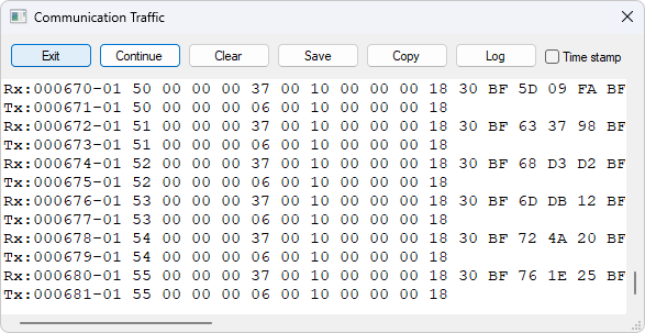
| This window shows only data sent and received by Modbus Slave. You can’t use it as a data sniffer. |
| Leave this window open while doing other commands. |
10. OLE/Automation
Automation (formerly known as OLE Automation) makes it possible for one application to manipulate objects implemented in another application.
An Automation client is an application that can manipulate exposed objects belonging to another application. This is also called an Automation controller.
An Automation server is an application that exposes programmable objects to other applications. Modbus Slave is an automation server.
That means you can use any program that supports VBA (Visual Basic for Applications) such as Visual Basic, Excel etc. to interpret and show the modbus data according to your specific requirements.
10.1. Excel example
You should display the Developer tab or run in developer mode when you want to write macros.
10.1.1. Excel 2007
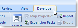
-
Click the Microsoft office button and then click Excel options.
-
Click popular and then select the show Developers tab in the ribbon check box.
Note the ribbon is part of the Microsoft fluent user interface.
10.1.2. Excel 2010, 2016
-
Click on the file tab.
-
Click options. Excel Options window will open.
-
On the left pane click Customize Ribbon.
-
On the right pane, under Main Tabs, check the Developer check box.
-
Click OK. The Developer tab should now show in the ribbon (right most tab).
10.1.3. Excel sample code
This example opens a window simulating Holding registers.
Modbus Slave is hidden but you can show it by uncomment the "ShowWindow" line. This will show one of the windows.
An example is also included with the Modbus Slave installation.
Start → All Programs → Modbus Slave → Excel Example
Public doc As Object
Public app As Object
Dim status As Integer
Dim n As Integer

Private Sub StartSlave_Click()
   ' Create an application object. You can only create 1 application object
   Set app = CreateObject("Mbslave.Application")

   ' Create a new Modbus Slave document (Data Window)
   ' This is the same as open a new data window in Modbus Slave
   ' You can create up to 50 Modbus Slave documents (Data Window)
   Set doc = CreateObject("Mbslave.Document")

   ' Show Modbus Slave
   ' res = doc.ShowWindow()

   ' Create doc2 if needed.
   ' Set doc2 = CreateObject("Mbslave.Document")

   ' Set one of 5 connection types.
   app.Connection = 1 ' Modbus TCP/IP

   ' TCP/IP settings.
   ' No need to set IP address. We listen to any address. (Default).
   app.ServerPort = 502
   app.IPVersion = 4

   ' Open the connection.
   res = app.OpenConnection()
   Range("D5").Value = res

   res = doc.SetupHoldingRegisters(1, 100, 8)
   doc.SRegisters(0) = 1     ' Modbus address 100
   doc.SRegisters(1) = -10   ' Note that the Index used counts from 0
   doc.URegisters(2) = 50000 ' no matter the Modbus address used.
   doc.URegisters(3) = 60000
   doc.Longs(4) = 10000      ' A long takes 2 registers
   doc.Floats(6) = 123.45    ' A float takes 2 registers
   ' Now a master can read 8 Holding registers with a mix of 3 data types

End Sub
10.2. Python example
This Python example opens a window and set all possible data formats.
import win32com.client as win32

SIGNED = 0
UNSIGNED = 1
HEX = 2
BINARY = 3
FLOAT_LE_BS = 4
FLOAT_BE = 5
DOUBLE_LE_BS = 6
DOUBLE_BE = 7
S32_LE_BS = 8
S32_BE = 9
FLOAT_LE = 10
FLOAT_BE_BS = 11
DOUBLE_LE = 12
DOUBLE_BE_BS = 13
S32_LE = 14
S32_BE_BS = 15

U32_BE = 17
U32_LE_BS = 18
U32_BE_BS = 19
U32_LE = 20

S64_BE = 21
S64_LE_BS = 22
S64_BE_BS = 23
S64_LE = 24

U64_BE = 25
U64_LE_BS = 26
U64_BE_BS = 27
U64_LE = 28

#Endianness
BE = 0
LE = 3
BE_BS = 2
LE_BS = 1

App = win32.Dispatch('Mbslave.Application')

App.Connection = 1
App.IPAddress = "127.0.0.1"

App.ServerPort = 502
App.OpenConnection

#Create a Modbus display window called Win1
Win1 = win32.Dispatch("Mbslave.Document")

# Setup 100 holding registers with slave ID 1, address 0 (40001)
Win1.SetupHoldingRegisters(1, 0, 100)
# Show the Modbus window
Win1.ShowWindow()
# Show 20 rows
Win1.Rows(1)

# Disable refresh for speed
Win1.EnableRefresh = False

# Set all different formats
# This sets how the value is displayed
# Use ByteOrder to set the actual endianness
Win1.SetFormat(0, SIGNED)
Win1.SetFormat(1, UNSIGNED)
Win1.SetFormat(2, HEX)
Win1.SetFormat(3, BINARY)

Win1.SetFormat(4, S32_BE)
Win1.SetFormat(6, S32_LE)
Win1.SetFormat(8, S32_BE_BS)
Win1.SetFormat(10, S32_LE_BS)

Win1.SetFormat(12, U32_BE)
Win1.SetFormat(14, U32_LE)
Win1.SetFormat(16, U32_BE_BS)
Win1.SetFormat(18, U32_LE_BS)

Win1.SetFormat(20, S64_BE)
Win1.SetFormat(24, S64_LE)
Win1.SetFormat(28, S64_BE_BS)
Win1.SetFormat(32, S64_LE_BS)

Win1.SetFormat(40, U64_BE)
Win1.SetFormat(44, U64_LE)
Win1.SetFormat(48, U64_BE_BS)
Win1.SetFormat(52, U64_LE_BS)

Win1.SetFormat(60, FLOAT_BE)
Win1.SetFormat(62, FLOAT_LE)
Win1.SetFormat(64, FLOAT_BE_BS)
Win1.SetFormat(66, FLOAT_LE_BS)

Win1.SetFormat(80, DOUBLE_BE)
Win1.SetFormat(84, DOUBLE_LE)
Win1.SetFormat(88, DOUBLE_BE_BS)
Win1.SetFormat(92, DOUBLE_LE_BS)

# Set all Names to used format
Win1.SetName(0, "SIGNED")
Win1.SetName(1, "UNSIGNED")
Win1.SetName(2, "HEX")
Win1.SetName(3, "BINARY")

Win1.SetName(4, "S32_BE")
Win1.SetName(6, "S32_LE")
Win1.SetName(8, "S32_BE_BS")
Win1.SetName(10, "S32_LE_BS")

Win1.SetName(12, "U32_BE")
Win1.SetName(14, "U32_LE")
Win1.SetName(16, "U32_BE_BS")
Win1.SetName(18, "U32_LE_BS")

Win1.SetName(20, "S64_BE")
Win1.SetName(24, "S64_LE")
Win1.SetName(28, "S64_BE_BS")
Win1.SetName(32, "S64_LE_BS")

Win1.SetName(40, "U64_BE")
Win1.SetName(44, "U64_LE")
Win1.SetName(48, "U64_BE_BS")
Win1.SetName(52, "U64_LE_BS")

Win1.SetName(60, "FLOAT_BE")
Win1.SetName(62, "FLOAT_LE")
Win1.SetName(64, "FLOAT_BE_BS")
Win1.SetName(66, "FLOAT_LE_BS")

Win1.SetName(80, "DOUBLE_BE")
Win1.SetName(84, "DOUBLE_LE")
Win1.SetName(88, "DOUBLE_BE_BS")
Win1.SetName(92, "DOUBLE_LE_BS")

# Set different values
Win1.SRegisters(0, -100)
Win1.SRegisters(1, 100)
Win1.URegisters(2, 43690)
Win1.URegisters(3, 65535)

Win1.ByteOrder = BE
Win1.Ints_32(4, -123456)
Win1.ByteOrder = LE
Win1.Ints_32(6, -123456)
Win1.ByteOrder = BE_BS
Win1.Ints_32(8, -123456)
Win1.ByteOrder = LE_BS
Win1.Ints_32(10, -123456)

Win1.ByteOrder = BE
Win1.UInts_32(12, 123456)
Win1.ByteOrder = LE
Win1.UInts_32(14, 123456)
Win1.ByteOrder = BE_BS
Win1.UInts_32(16, 123456)
Win1.ByteOrder = LE_BS
Win1.UInts_32(18, 123456)

Win1.ByteOrder = BE
Win1.Ints_64(20, -123456)
Win1.ByteOrder = LE
Win1.Ints_64(24, -123456)
Win1.ByteOrder = BE_BS
Win1.Ints_64(28, -123456)
Win1.ByteOrder = LE_BS
Win1.Ints_64(32, -123456)

Win1.ByteOrder = BE
Win1.UInts_64(40, 123456)
Win1.ByteOrder = LE
Win1.UInts_64(44, 123456)
Win1.ByteOrder = BE_BS
Win1.UInts_64(48, 123456)
Win1.ByteOrder = LE_BS
Win1.UInts_64(52, 123456)

Win1.ByteOrder = BE
Win1.Floats (60, 123.456)
Win1.ByteOrder = LE
Win1.Floats (62, 123.456)
Win1.ByteOrder = BE_BS
Win1.Floats(64, 123.456)
Win1.ByteOrder = LE_BS
Win1.Floats(66, 123.456)

Win1.ByteOrder = BE
Win1.Doubles(80, 123.456)
Win1.ByteOrder = LE
Win1.Doubles(84, 123.456)
Win1.ByteOrder = BE_BS
Win1.Doubles(88, 123.456)
Win1.ByteOrder = LE_BS
Win1.Doubles(92, 123.456)

# Refresh
Win1.EnableRefresh = True

Win1.ResizeAllColumns ()
Win1.ResizeWindow()

print (Win1.GetName(1))

_ = input("Press ENTER to quit:")
10.3. Connection Functions/Properties
The following properties and functions do the same as you setup in the connection dialog (F3).
10.3.1. Connection
Connection selects the desired connection. A serial port or one of the Ethernet connections can be selected.
Property Connection as Integer
- Valid values
-
0 = Serial port
1 = Modbus TCP/IP
2 = Modbus UDP/IP
3 = Modbus RTU over TCP/IP
4 = Modbus RTU over UDP/IP
Connection = 010.3.2. BaudRate
Applicable only for Connection = 0
Property BaudRate as Long
- Valid values
-
300
600
1200
2400
4800
9600 (Default)
14400
19200
38400
56000
57600
115200
128000
153600
230400
256000
460800
921600
BaudRate = 960010.3.3. DataBits
Applicable only for Connection = 0
Property DataBits as Integer
- Valid values
-
7
8 (Default)
DataBits = 810.3.4. Parity
Applicable only for Connection = 0
Property Parity as Integer
- Valid values
-
0 = None
1 = Odd
2 = Even (Default)
Parity = 210.3.5. StopBits
Applicable only for Connection = 0
Property StopBits as Integer
- Valid values
-
1 (Default)
2
StopBits = 110.3.6. SerialPort
Applicable only for Connection = 0
Property SerialPort as Integer
- Valid values
-
1…255
Default value = 1
SerialPort = 110.3.7. ServerPort
Applicable only for Connection = 1…4
Property ServerPort as Long
- Valid values
-
0…65535
Default value = 502
ServerPort = 50210.3.8. IPVersion
Applicable only for Connection = 1…4
Property IPVersion as Integer
- Valid values
-
4 = IP Version 4 (Default)
6 = IP Version 6
IPVersion = 410.3.9. AnyAddress
Applicable only for Connection = 1…4
Property AnyAddress as Integer
- Valid values
-
0 = Any address = false
1 = Any address = true (Default)
AnyAddress = 110.3.10. IgnoreUnitID
Applicable only for Connection = 1…4
Property IgnoreUnitID as Integer
- Valid values
-
0 = Ignore unit ID = false
1 = Ignore unit ID = true (Default)
IgnoreUnitID = 110.3.11. OpenConnection
Opens the connection selected with the Connection property.
Function OpenConnection() As Integer
Return Value:
Zero if success. Nonzero value if failed.
Public app As Object
Dim res As Integer
' Create an object to Modbus Slave
Set app = CreateObject("Mbslave.Application")
app.Connection = 1 ' Select Modbus TCP/IP
app.IPVersion = 4
' app.IPAddress = "192.168.1.27"    ' No need to setup if AnyAddress = 1. Modbus Slave listen on all.
app.ServerPort = 502
res = OpenConnection()Public app As Object
Dim status As Integer
' Create an object to Modbus Slave
Set app = CreateObject("Mbslave.Application")
app.Connection = 0 ' Mode is serial port
app.SerialPort = 1 ' Com port 1
app.BaudRate = 9600 ' 9600 baud
app.Parity = 0 ' None parity
app.Mode = 0 ' RTU mode
status = app.OpenConnection()10.3.12. CloseConnection
Function CloseConnection() As Integer
- Return Value
-
Zero if success. Nonzero value if failed.
10.3.13. ShowCommunicationTraffic
Function ShowCommunicationTraffic()
Shows the communication traffic window.
10.3.14. CloseCommunicationTraffic
Function CloseCommunicationTraffic()
Closes the communication traffic window if shown.
10.4. Automation setup Functions
The following functions do the same as you setup in the read/write definition dialog (F8).
Read functions are associated with a Modbus Slave document. (The window with data)
.Example
Res = doc.SetupDiscreteInputs (1, 100, 5)
Coils (0) = 1    ' Address 100 = 1
Coils (1) = 0    ' Note that the index used in Coils starts from 0
Coils (2) = 1    ' no matter the address used.
Coils (3) = 0
Coils (4) = 1
' Now the Master reads 1, 0, 1, 0, 1 when read 5 discrete inputs starting from address 100
10.4.1. SetupCoils
Function SetupCoils(SlaveID As Integer, Address As Long, Quantity As Integer) As Integer
- Return Value
-
True if success. False if not success
- Parameters
-
SlaveID: The slave address 1 to 255
Address: The data address (Base 0)
Quantity: The number of data. 1 to 10000
10.4.2. SetupDiscreteInputs
Function SetupDiscreteInputs(SlaveID As Integer, Address As Long, Quantity As Integer) As Integer
- Return Value
-
True if success. False if not success
- Parameters
-
SlaveID: The slave address 1 to 255
Address: The data address (Base 0)
Quantity: The number of data. 1 to 10000
10.4.3. SetupHoldingRegisters
Function SetupHoldingRegisters(SlaveID As Integer, Address As Long, Quantity As Integer) As Integer
- Return Value
-
True if success. False if not success
- Parameters
-
SlaveID: The slave address 1 to 255
Address: The data address (Base 0)
Quantity: The number of data. 1 to 10000
10.4.4. SetupInputRegisters
Function SetupInputRegisters(SlaveID As Integer, Address As Long, Quantity As Integer) As Integer
- Return Value
-
True if success. False if not success
- Parameters
-
SlaveID: The slave address 1 to 255
Address: The data address (Base 0)
Quantity: The number of data. 1 to 10000
10.4.5. ShowWindow
As default Modbus document windows are hidden. The ShowWindow function makes Modbus Poll visible and shows the document with data content.
Function ShowWindow()
- Parameters
-
This function has no parameters.
- Return value
-
None
10.4.6. GetName
Gets the name of a value.
Function GetName(Index As Integer) As String
- Parameters
-
Index: Index 0 corresponds to the first Modbus address.
- Return value
-
The name.
10.4.7. SetName
Changes the name of a value.
Function SetName(Index As Integer, Name As String)
- Parameters
-
Index: Index 0 corresponds to the first Modbus address.
Name: The name of the value cell. - Return value
-
None
10.4.8. AutoIncrement
Sets automatic increment of a value.
Property AutoIncrement(Index As Integer) As Boolean
- Parameters
-
Index: Index 0 corresponds to the first Modbus address.
- Syntax
-
AutoIncrement(Index) [=newvalue]
10.4.9. AutoDecrement
Sets automatic decrement of a value.
Property AutoDecrement(Index As Integer) As Boolean
- Parameters
-
Index: Index 0 corresponds to the first Modbus address.
- Syntax
-
AutoDecrement(Index) [=newvalue]
10.4.10. FormatAll
Format all value cells with the selected format.
Function FormatAll(Format As Integer)
- Parameters
-
Format: The format of the value cell.
- Return value
-
None
10.4.11. GetFormat
Gets the display format of the Modbus value.
Function GetFormat(Index As Integer) As Integer
- Parameters
-
Index: Index 0 corresponds to the first Modbus address.
- Return value
| ID | Format |
|---|---|
0 |
Signed |
1 |
Unsigned |
2 |
Hex |
3 |
Binary |
4 |
Float little-endian byte swap |
5 |
Float big-endian |
6 |
Double little-endian byte swap |
7 |
Double big-endian |
8 |
32-bit Signed little-endian byte swap |
9 |
32-bit Signed big-endian |
10 |
Float little-endian |
11 |
Float big-endian byte swap |
12 |
Double little-endian |
13 |
Double big-endian byte swap |
14 |
32-bit Signed little-endian |
15 |
32-bit Signed big-endian byte swap |
17 |
32-bit Unsigned big-endian |
18 |
32-bit Unsigned little-endian byte swap |
19 |
32-bit Unsigned big-endian byte swap |
20 |
32-bit Unsigned little-endian |
21 |
64-bit Signed big-endian |
22 |
64-bit Signed little-endian byte swap |
23 |
64-bit Signed big-endian byte swap |
24 |
64-bit Signed little-endian |
25 |
64-bit Unsigned big-endian |
26 |
64-bit Unsigned little-endian byte swap |
27 |
64-bit Unsigned big-endian byte swap |
28 |
64-bit Unsigned little-endian |
| This setting is only for display. You still need to use byteOrder to get the correct endianness when using Get/Set value functions. |
10.4.12. SetFormat
Change the display format of the Modbus values. See Format values above.
Function SetFormat(Index As Integer, Format As Integer)
- Parameters
-
Index: Index 0 corresponds to the first Modbus address.
Format: The format of the value cell. - Return value
-
None
10.4.13. ResizeWindow
Resize an opened window to fit the grid.
Function ResizeWindow()
- Parameters
-
This function has no parameters.
- Return value
-
None
10.4.14. ResizeAllColumns
Resize all columns to fit the values inside the cells.
Function ResizeAllColumns()
- Parameters
-
This function has no parameters.
- Return value
-
None
10.4.15. Rows
Specify the number of rows in the grid.
Function Rows(NumberRows)
- Parameters
-
NumberRows: Number of rows in the grid.
| ID | Description |
|---|---|
0 |
10 Rows (Default) |
1 |
20 Rows |
2 |
50 Rows |
3 |
100 Rows |
4 |
Fit to quantity |
- Return value
-
None
10.4.16. EnableRefresh
Set to False while setting a lot of cell data such as names, values, and formatting. Set True when done.
Property EnableRefresh As Boolean
# Disable refresh for speed
Win1.EnableRefresh = False
#... Some cell data settings
# Refesh
Win1.EnableRefresh = True
10.4.17. ReadWriteDisabled
Used to temporary enable or disable the communication for this window.
Property ReadWriteDisabled As Boolean
10.5. Automation data properties
The below properties are used to set or get values in the internal write/read arrays in Modbus Slave. The Index used is not a Modbus Address. The Index always counts from 0 no matter of the address used. The data properties are associated with a Modbus Slave document. (The window with data)
Example 1:
' doc is assumed created first. See Excel example.
doc.SRegisters(0) = 1
doc.SRegisters(1) = 10
doc.SRegisters(2) = 1234
Example 2 with floating point values:
doc.Floats(0) = 1.3
doc.Floats(2) = 10.5
doc.Floats(4) = 1234.12
10.5.1. Coils
Property Coils(Index As Integer) As Integer
- Description
-
Sets a coil in the write array structure or return a coil from the read array.
- Syntax
-
Coils(Index) [=newvalue]
10.5.2. SRegisters
Property SRegisters(Index As Integer) As Integer
- Description
-
Sets a register in the write array structure or return a register from the read array.
- Syntax
-
SRegisters(Index) [=newvalue]
10.5.3. URegisters
Property URegisters(Index As Integer) As Long
- Description
-
Sets a register in the write array structure or return a register from the read array.
- Syntax
-
URegisters(Index) [=newvalue]
10.5.4. Ints_32
Property Ints_32(Index As Integer) As Double
- Description
-
Sets a 32-bit integer in the write array structure or return an integer from the read array.
- Syntax
-
Ints_32(Index) [=newvalue]
10.5.5. UInts_32
Property UInts_32(Index As Integer) As Double
- Description
-
Sets a 32-bit unsigned integer in the write array structure or return an unsigned integer from the read array.
- Syntax
-
UInts_32(Index) [=newvalue]
10.5.6. Ints_64
Property Ints_64(Index As Integer) As Double
- Description
-
Sets a 64-bit integer in the write array structure or return an integer from the read array.
- Syntax
-
Ints_64(Index) [=newvalue]
10.5.7. UInts_64
Property UInts_64(Index As Integer) As Double
- Description
-
Sets a 64-bit unsigned integer in the write array structure or return an unsigned integer from the read array.
- Syntax
-
UInts_64(Index) [=newvalue]
10.5.8. Floats
Property Floats(Index As Integer) As Single
- Description
-
Sets a float in the write array structure or returns a float from the read array.
- Syntax
-
Floats(Index) [=newvalue]
10.5.9. Doubles
Property Doubles(Index As Integer) As Double
- Description
-
Sets a double in the write array structure or return a double from the read array.
- Syntax
-
Doubles(Index) [=newvalue]
10.5.10. ByteOrder
Property ByteOrder As Integer
- Description
-
Sets the byte order used by Ints_32, UInts_32, Ints_64, UInts_64, Floats and Doubles properties.
| ID | Endianness |
|---|---|
0 |
Big-endian (Default) |
1 |
Little-endian byte swap |
2 |
Big-endian byte swap |
3 |
Little-endian |
Example for Ints_32:
Byte Order: Big-endian
The decimal number 123456789 or in hexadecimal 07 5B CD 15
Order as they come over the wire in a Modbus message: 07 5B CD 15
- Syntax
-
ByteOrder [=newvalue]